TOST Brake Assembly 30-63A Spare Parts
Please See "Important Shipping Information" Below
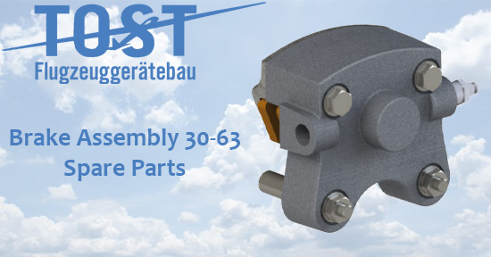
TOST Brake Assembly 30-63A Spare Parts
General Description
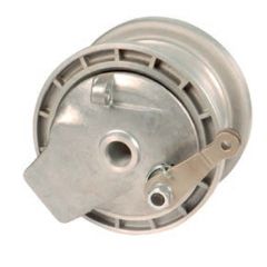
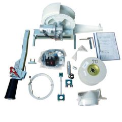
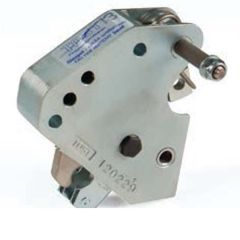
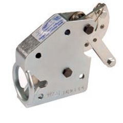
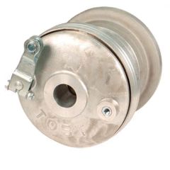
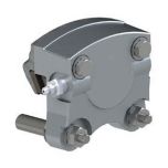
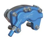
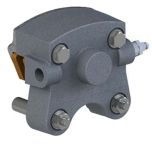
TOST Brake Assembly 30-63A Spare Parts - by Cleveland is designed as a floating brake caliper and can be mounted to 6′′ disk brake wheels of the series Classic. The simple but robust design of the brake assembly ensures a long service time and easy maintenance with good deceleration values.
Always use TOST Tires and Tubes when available.
Select the right Tire, Tube & Wheel for your sailplane by referencing our Tire, Tube & Wheel Selection Guide.
TOST Brake Assembly 30-63A Spare Parts price varies depending on selection. Use above dropdown box for selections and final price.

|
P/N SKU |
Desc | Fluid | Remarks | No. |
|
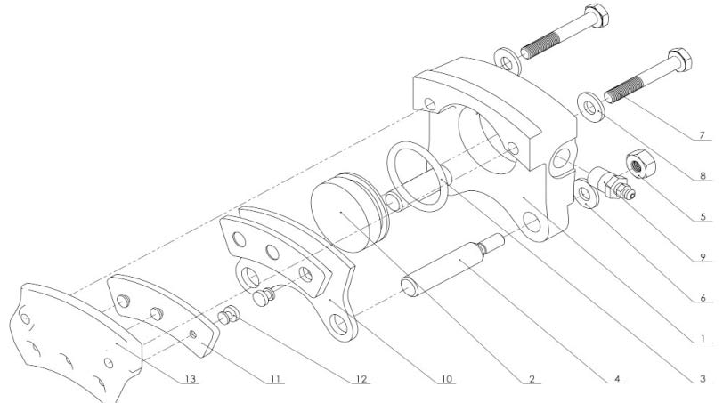
076829 6257 |
Piston Housing | N/A | 1 | |
|
076825 6258 |
Piston | N/A | 2 | |
|
076834 6260 |
O-Ring |
Mineral Fluid |
3 | |
|
076835 6171 |
O-Ring |
DOT4 |
3 | |
|
075870 6261 |
Anchor Bolt | N/A | 5“ Cleveland, 5“/6“ SBP Penta |
4 |
|
075881 6263 |
Nut Anchor Bold | N/A | 5 | |
| 075869 | Anchor Bolt | N/A | 4“ SRT Tria, 4“SB Classic, 5“ SB Classic | 4 |
|
075882 6264 |
Washer Anchor Bolt | N/A | 6 | |
|
075873 6266 |
Housing Bolt | N/A | 7 | |
| 075882 | Washer Housing Bolt | N/A | 8 | |
|
075832 6267 |
Bleeder Valve Complete | N/A | also Stahlbus bleeder valve possible, quod vide | 9 |
|
076872 6269 |
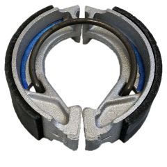
Pressure Plate With Brake Lining | N/A | 10-12 | |
|
076862 6270 |
Brake Lining | N/A | 11 | |
|
075861 6271 |
Rivet Brake Lining | N/A | 12 | |
|
076871 6273 |
Back Plate With Brake Lining | N/A | 11-13 | |
|
076865 6272 |
Service Kit for Brake Lining Replacement | N/A | 2 x brake lining, 4 x rivet | 11, 12 |
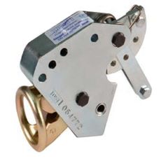
| 076891 | Anchor Plate for Brake Assembly 30-63A |
Brake lining wear limit:
The minimum replacement thickness on organic linings is 2.5 mm.
The total thickness of brake linings at any point must not be less than this value.
Installation note:
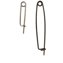
After mounting the brake assembly, tighten the hexagonal bolt with a tightening
torque of (60 in-lb) and secure with locking wire 0.8 mm Spec. MS-20995.
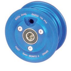
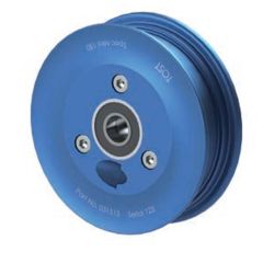
For many years disk brake wheels (SB) have been the first choice as a braked wheel for gliders, motor gliders, Ultralight aircraft, powered aircraft as well as for helicopters and gyrocopters. Due to the facts that the brake force can be well-applied, the automatic re-adjustment of the lining abrasion and the high, stable braking power, disk brake wheels provide an ideal braking efficiency in all situations and ensure the safe realization of a flight.
Remark to the tables:
The indication of the mass of a wheel includes the wheel hub with ball bearings and brake disk. You can find the mass of the tires/tubes and brake assemblies in the correspondent chapters of the catalog.
Pay attention to the following points to ensure the operational function of the brake system in your aircraft:
- The min. thickness of the brake disk may not be underrun, see page 29 of the TOST Catalog
- The minimum thickness of the brake lining may not be underrun, see page 50 of the TOST Catalog
- Watch out for sealings and boltings so that no leakage may occur
- Change the brake fluid regularly
- Never mix brake fluid DOT 4 and Mineral Fluid
- The brake system should be well-bleeded
Maintenance notes for brake disk
- Inspect brake disk for cracks, excessive wear and tear, grooves, corrosion and deformation.
- Remove corrosion and smooth smaller nicks with fine emery paper (400 grain).
- Replace the brake disk, if it is worn beyond the wear limit (see below). Measure this minimum at two or three spots.
- Replace the brake disk if it has an axial throw of 0.2 mm.
- Brake disks are surface-treated only for special applications. A rust film of varying degree may form on the brake disk. That can be removed with one or two parking brake operations.
- If rust has progressed further, it may be necessary to dismantle the disk from the wheel so that both disk surfaces can be cleaned properly. First use a steel brush, then follow with 220 grain emery paper. Finally polish with 400 grain emery paper. This procedure may allow you to continue using the brake disk.
| Disk Thickness mm | Wear limit mm |
| 1.5 | 1.3 |
| 2.0 | 1.7 |
| 4.0 | 3.3 |
| 5.0 | 4.3 |
| 6.0 | 5.2 |
| 6.5 | 5.5 |
| 8.0 | 7.0 |
Notes to aircraft tires
Tire exchange
Removal:
- Jack up aircraft at specified point.
- Deflate tire completely before removing wheel unit.
- Do not unscrew the valve insert until the tire pressure has dropped to 0.2 bar.
- Remove wheel from axle.
- Loosen wheel bead from the hub shoulder with a rubber or plastic hammer.
- Undo wheel bolts (with 5 mm hexagon key), remove bolts and washers, split hub halves.
Mounting:
- Tires and wheel hubs must be clean and dry.
- Do not apply excessive force when replacing a wheel.
- Apply adhesive agent (or talcum powder) to the hub shoulder.
- Remove dirt, sand, labels, etc. from the tire. Apply a moderate amount of talcum powder to reduce friction between tube and tire. Caution: Too much talcum has the opposite effect.
- Fill air into tube (placed in the tire) until it is evenly round. Remove nut and washer from valve.
- Place tire (red mark at valve hole) and tube on the wheel half with the valve hole, push valve through valve hole
- Push other wheel half onto tire, match bolt holes with centering shaft.
- Insert wheel bolts, washers and any nuts, and tighten to the correct torque (M6: 9 to 10 Nm). Tighten bolts diagonally.
- Place a tire in a safety cage when inflating it to mounting pressure for the first time. If you do not have a safety cage, take great care when inflating the tire. Inflate the tire to mounting pressure. The mounting pressure is 10% more than the specified operating pressure. Check carefully for leaks. Leave to adjust at this pressure for 12 to 24 hours. Once the tire shows no leaks and is at operating pressure, the wheel unit can be mounted on the aircraft.
- Make sure that the wheel unit is mounted perfectly balanced to avoid vibration and excessive wear.
Red Dot:
Larger aircraft tires are marked with a red dot. This is an indication of the lightest spot of the tire. The valve must be placed at this point to eliminate or minimize a balance/vibration problem of the tire.
WARNING:
An inflated tire is a potentially explosive device – treat it with the correct equipment and precautions!
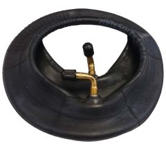
Notes on inner tubes
Aircraft tubes are made from natural rubber, and they are slightly underdimensioned so that it is easier to install them in a new tire. The layers of an aircraft tire are made of nylon – they therefore tend to become larger with use.
The inner tube also increases in size, adapting to the larger inside diameter of the tire. If a tube enlarged in this way is later fitted in a new tire, it can happen that it is too big for the inside of the tire, with the result that the tube may crease.
These creases may rub through during operation, causing the tube to lose pressure. Rubbing through slowly results in slow pressure loss – the pilot is thus warned before a dangerous situation arises. If the tube tears during a start, the pilot will fail
to notice that he is flying with a flat tire.
Taking into consideration all the risks involved with fitting an old tube into a new tire, it is advisable always to fit new inner tubes in new tires.
Tire maintenance instructions
- Maintain stipulated air pressure, check at regular intervals! Underpressure results in reduced load capacity and shortens service life.
- Inspect tires at regular intervals for damages, shredding, flat areas and foreign objects.
- Wheel units must be mounted perfectly balanced. Wheel imbalance can result in damage to bearings and brake drums.
- Keep tires free of oil, grease, brake fluid and tar. Clean tires with rag soaked with petrol, then wash off with soap and water.
IMPORTANT SHIPPING INFORMATION
For items marked "Typically Stocked," please select "With Next Restock Order". This helps avoid additional Special Order shipping charges. If the item is in stock, it will ship from our warehouse the same or next business day in accordance with our shipping policies.
For all "SPO" (Special Order) part numbers, please select the shipping option that best matches your preferred delivery method.
In the event a "Typically Stocked" item is temporarily out of stock, we will contact you to confirm your preferred shipping method before processing the order.
See "Tech Data" tab for Description and Fluid.