Creating an account has many benefits:
- See order and shipping status
- Track order history
- Check out faster
Digital Water Meter
General Description
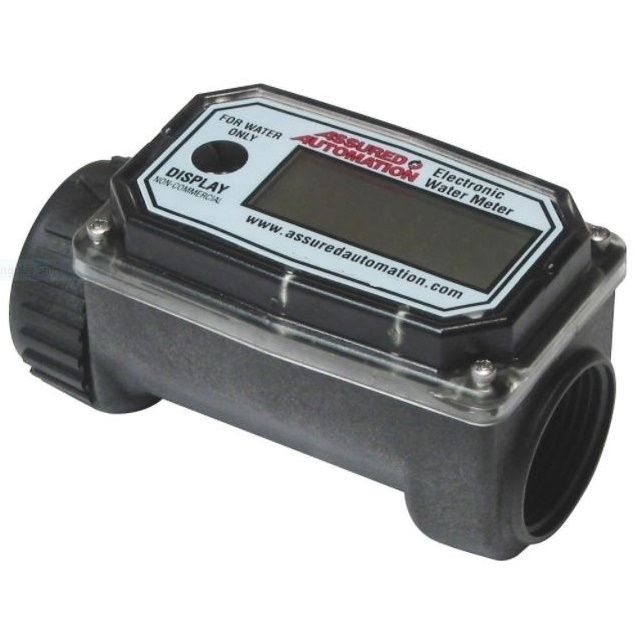
Digital Water Meter - This electronic water meter easily installs at the end of a hose for accurate sailplane water ballast loading. Visit your local hardware store for hose, PVC hose fittings and shutoff valve. Typically when filling a wing tank place a wingstand under the first wing you're filling or both wings if possible so that the wings are horizontal. After you reach the calculated water quantity (gallons or liters) turn off the water then repeat with other wing tank(s). Check your flight, operating or maintenance manual for details on loading water ballast for your sailplane.
The water meter has a large easy to read display and compact lightweight design making it easy to handle. A rugged nylon housing and sealed electronic circuitry provides years of durable use in almost any condition. Two AAA batteries power the small microprocessor for a year and are very easy to replace.
W&W typically stocks Digital Water Meters.
use above selection for Digital Water Meter.


- Flow Range: 3-30 Gallons Per Minute, 10-100 Liters Per Minute
- Rugged Construction
- Designed for Indoor/Outdoor Use
- Digital Display
- Large 1/2" Tall Digits
- Maximum Batch Total 9,999
- Approximate Battery Life is 9,000 hrs
- Meter Made in America
| Materials | Nylon Housing Nylon Turbine & Supports 316SS Rings Tungsten Carbide Shafts Ceramic Bearings |
| End Connections | NPT Threaded (1" female) Garden Hose Adapters Available |
| Temperature Range | 130°F |
| Maximum Pressure | 150psi |
| Accuracy | ± 2.5% (typical... can vary up to 5%) |
| Weight |
1.1 lbs.
|
Installation
- If necessary, remove nozzle from hose.
- Apply pipe sealant to all threaded connections.
- Attach meter to hose with arrow on outlet port pointed in the direction of flow.
- If necessary, attach nozzle to meter.
- Hand tighten the meter at the housing ends. Do not use a wrench or similar tools to tighten the meter housing. The plastic housing could be damaged.
Operation
The meter maintains two totals. The batch total may be reset to measure flow during a single use. The cumulative total provides continuous measurement and may not be manually reset. The batch total is labeled as TTL1. The cumulative total is labeled TTL2.
When the cumulative total reaches a maximum reading of 9999, it will automatically reset to zero.
Press the DISPLAY button briefly to switch between the batch and cumulative total.
Activate the Meter
Turn the meter ON by starting water flow or briefly pressing the DISPLAY button. The meter will display the batch or cumulative total from last use.
Press DISPLAY briefly to display the batch total. Hold the DISPLAY button down for three seconds to reset the batch total to zero.
The meter is programmed to turn off automatically if not used for about one minute.
Calibration
This meter has a permanent factory calibration for measuring water. If installed and used correctly, inaccuracies of no greater than ±5% will be obtained.
Maintenance
Proper handling and care will extend the life and service of the meter.
Turbine Rotor
The meter is virtually maintenance-free. However, it is important the rotor moves freely. Keep the meter clean and free of contaminants.
If the rotor does not turn freely, apply a penetrating lubricant on the rotor, shaft, and bearings. Remove any debris or deposits from the rotor using a soft brush or small probe. Be careful not to damage the turbine rotor or supports.
Caution: Blowing compressed air through the turbine assembly could damage the rotor.
Battery Replacement
The meter is powered by two AAA alkaline batteries which may be replaced while the meter is installed. When batteries are removed or lose power, the batch and cumulative totals reset to zero but the factory calibration is retained.
If the display becomes dim or blank, replace the batteries as follows:
- Remove the four Phillips-head screws from the face of the meter and lift the faceplate from the turbine.
- Remove the old batteries and clean any corrosion from the terminals.
- Install new batteries. Make sure the positive post is in the correct position.
- When the batteries are replaced, the faceplate will power ON. Check the display to ensure normal functions have resumed before assembling again.
- Reseat batteries, if necessary, and position the faceplate on the turbine housing. To avoid moisture damage, make sure the O-ring is fully seated. Tighten the four screws on the faceplate.


