Winter Instruments 7 FMS Airspeed Indicator (ASI) 57mm
7 FMS Airspeed Indicator
57mm ASI
Winter Instruments 7 FMS Airspeed Indicator (ASI) 57mm

General Description
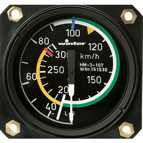
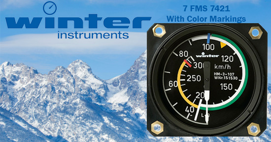
Winter Instruments 7 FMS Airspeed Indicator 57mm - Airspeed indicators measure the difference between total pressure and static pressure. The total (or measured) pressure is sensed by a pitot tube positioned at the stagnation point of the airstream and is carried to the airspeed indicator by a hose. A static pressure sensor can also be connected.The measuring element is an open diaphragm unit with excellent elastic properties; hysteresis (differences between advance and return movement) and secondary elastic effects are negligible. The effect total pressure and static pressure acts on the diaphragm, causing a deformation, that is transferred to the pointer by a linkage and gear mechanism. The different operating ranges of the aircraft can be identified by colour markings on the airspeed indicator dial. The instruments are insensitive to shock and vibration.
The most popular 57 mm ASI in the USA is 7423. W&W typically stocks the ASI models highlighted in the table (7412 @12 O'clock, 7423 @12 O'clock and 7421 @6 O'clock). *Please allow approximately 4 weeks Winter production time for all other ASI models and Factory Color Marked Airspeed Indicators.
Airspeed Indicators come in two different sizes:
- 57mm 7 FMS
- 80mm 6 FMS
Technical Description
Purpose: Pilot airspeed indicator for indication of the relative airspeed of gliders and microlights.
Principal mode of operation: The instrument works by measurement of the pilot pressure, by means of an open diaphragm cell, as difference between total pressure and static pressure.
Scale graduation:
- 7 FMS 2 and 7 FMS 5: 360° scale with linear graduation
- 7 FMS 4: 510° scale with non–linear graduation
Factory Color Marking
Color markings can be put on the instrument scale to identify the operating ranges and the limiting performance of the aircraft. The type series numbers given in the above table are only applicable to types 7 FMS 2, 7 FMS 4 and 7 FMS 5 airspeed indicators without color marking on the indicator scale. In all other cases, the part number should be obtained from the technical documents of the aircraft manufacturer or by checking with Gebr. Winter & Co. KG.
*Please allow approximately 4 weeks Winter Instruments production time for Factory Installed Color Markings.
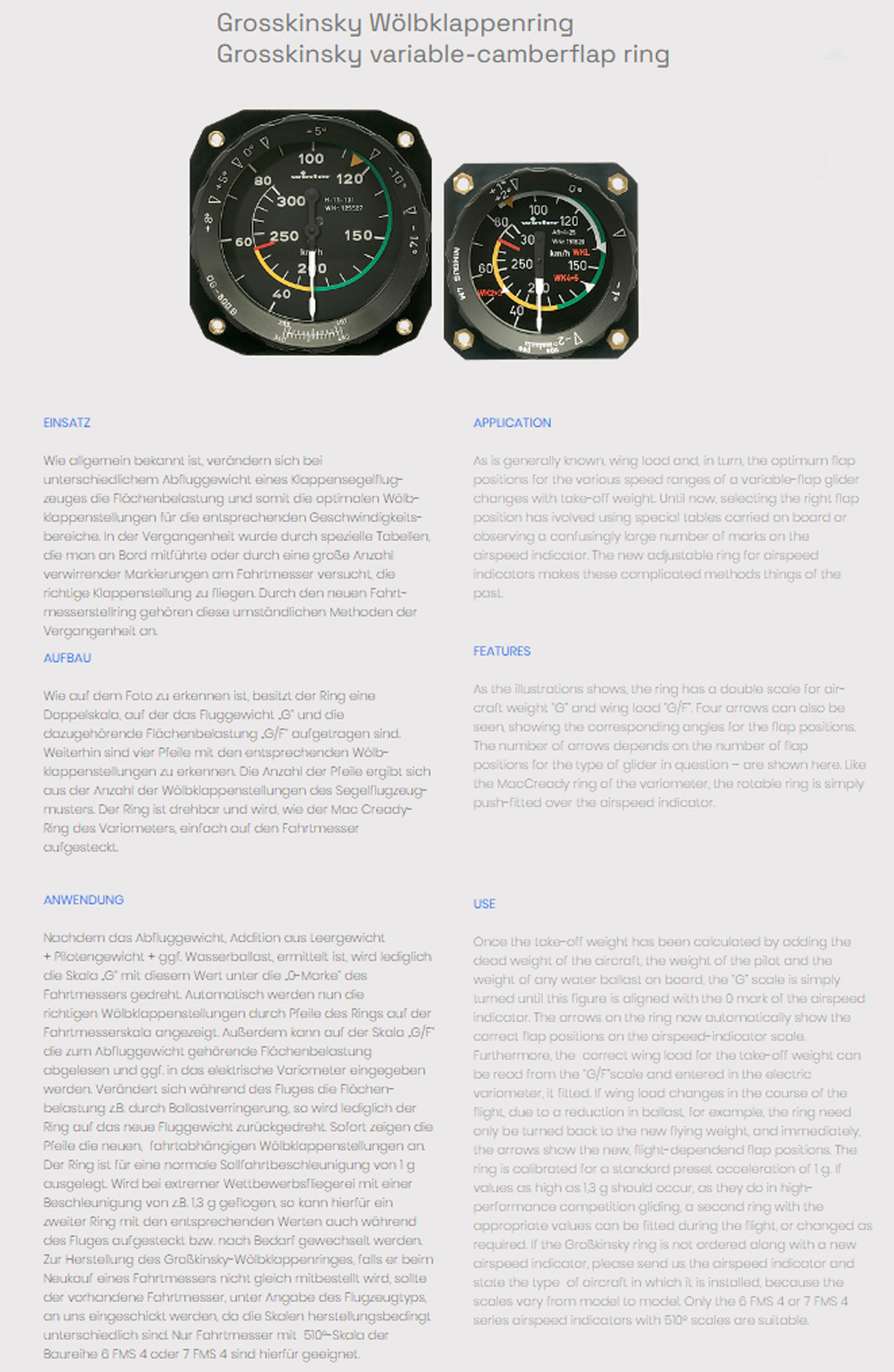
Grosskinsky Variable Camberflap Ring
Grosskinsky Variable Camberflap Ring - As is generally known, wing load and, in turn, the optimum flap positions for the various speed ranges of a variable-flap glider changes with take-off weight. Until now, selecting the right flap position has ivolved using special tables carried on board or observing a confusingly large number of marks on the airspeed indicator. The new adjustable ring for airspeed indicators makes these complicated methods things of the past.
*Please allow approximately 4 weeks Winter Instruments production time for Grosskinsky Variable Camberflap RIngs.
Maintenance Insructions
Leak Testing should be carried out at least every 2 years. Otherwise, the instrument does not require any maintenance.
The manufacturer recommends airspeed indicators be subject to retesting after 5 years.
Retesting and Repair
The service condition and accuracy of measurement of the ASI is normally retained over a long period. For obvious malfunction the unit should be subjected to an investigation at the manufacturer or a suitable aircraft engineering company. It should be packed to protect it from impacts and connections should be sealed. Under no circumstances should you interfere with the measuring mechanism of the airspeed indicator.
Accompanying Documents
-
New Instrument
Test certificate EASA Form One, POE
Installation and maintenance instructions -
Used Instrument
Test certificate EASA Form One, POE
Winter Instruments ASI price varies depending on selections above.
| Item # | Range | Diameter | Depth | Weight | Dial |
|
7211 7 FMS 211 |
0–200 km/h | 57 mm ø | 57 mm | 0,075 kg | 360° |
|
7212 7 FMS 212 |
0–120 mph | 57 mm ø | 57 mm | 0,075 kg | 360° |
|
7213 7 FMS 213 |
0–100 knots | 57 mm ø | 57 mm | 0,075 kg | 360° |
|
7221 7 FMS 221 |
0–250 km/h | 57 mm ø | 57 mm | 0,075 kg | 360° |
|
7222 7 FMS 222 |
0–160 mph | 57 mm ø | 57 mm | 0,075 kg | 360° |
|
7223 7 FMS 223 |
0–140 knots | 57 mm ø | 57 mm | 0,075 kg | 360° |
|
7401 7 FMS 401 |
0–200 km/h | 57 mm ø | 57 mm | 0,075 kg | 510° |
|
7402 7 FMS 402 |
0–140 mph | 57 mm ø | 57 mm | 0,075 kg | 510° |
|
7403 7 FMS 403 |
0–100 knots | 57 mm ø | 57 mm | 0,075 kg | 510° |
|
7411 7 FMS 411 |
0–250 km/h | 57 mm ø | 57 mm | 0,075 kg | 510° |
|
7412 7 FMS 412 |
0–160 mph | 57 mm ø | 57 mm | 0,075 kg | 510° |
|
7413 7 FMS 413 |
0–140 knots | 57 mm ø | 57 mm | 0,075 kg | 510° |
|
7421 7 FMS 421 |
0–300 km/h | 57 mm ø | 57 mm | 0,075 kg | 510° |
|
7422 7 FMS 422 |
0–180 mph | 57 mm ø | 57 mm | 0,075 kg | 510° |
|
7423 7 FMS 423 |
0–160 knots | 57 mm ø | 57 mm | 0,075 kg | 510° |
|
7441 7 FMS 441 |
0–350 km/h | 57 mm ø | 57 mm | 0,075 kg | 510° |
|
7442 7 FMS 442 |
0–220 mph | 57 mm ø | 57 mm | 0,075 kg | 510° |
|
7443 7 FMS 443 |
0–200 knots | 57 mm ø | 57 mm | 0,075 kg | 510° |
|
7511 7 FMS 511 |
0–300 km/h | 57 mm ø | 57 mm | 0,075 kg | 360° |
|
7512 7 FMS 512 |
0–180 mph | 57 mm ø | 57 mm | 0,075 kg | 360° |
|
7513 7 FMS 513 |
0–160 knots | 57 mm ø | 57 mm | 0,075 kg | 360° |
|
7521 7 FMS 521 |
0–350 km/h | 57 mm ø | 57 mm | 0,075 kg | 360° |
|
7522 7 FMS 522 |
0–220 mph | 57 mm ø | 57 mm | 0,075 kg | 360° |
|
7523 7 FMS 523 |
0–200 knots | 57 mm ø | 57 mm | 0,075 kg | 360° |
Weight: 7 FMS 2, 7 FMS 4 and 7 FMS 5: 0,9 kg
Indication errors:
- at room temperature: 0–100 km/h:± 2 km/h above 100 km/h: ± 3 km/h
- at –30°C to + 50°C: 0–100 km/h:± 3 km/h above 100 km/h: ± 5 km/h
Application Limits
Maximum operating height: 12.000 m
Operating temperature range: –30°C to + 50°C
Magnetic Effect: No deflection of the compass needle at any distance between airspeed indicator and aircraft compass.
Overpressure resistance: The maximum indicated airspeed may be exceeded by 20%.
Vibration resistance: 5 – 50 Hz: maximum amplitude 0,25 m
maximum acceleration 1,5 g
50 – 400 Hz: maximum acceleration 0,5 g


