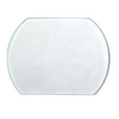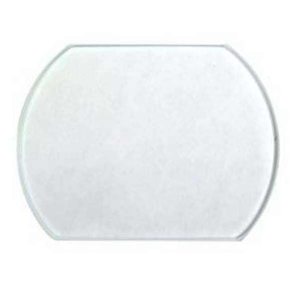
Airpath Compass Lens
Manufacturer Part Number: CB21-913X
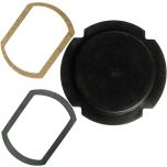
Airpath Compass Lens
General Description
Airpath Compass Lens (STD) CB21–913X - replacement lens for Airpath Compass.
Scope of delivery: one lens.
W&W typically stocks Airpath Compas Lens CB21-913X.

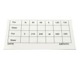
COMPENSATING INSTRUCTIONS FOR AIRPATH COMPASSES
Before attempting to compensate compass, every effort should be made to place the aircraft in simulated flight conditions. Check to see that doors are closed, flaps are in retracted position, throttles set at cruise position, engine(s) operating, and aircraft in a level attitude. All electrical switches, generators, radios, etc., should be in the position they will normally be for navigation flight.
COMPENSATION
- Set adjustment screws of compensator on zero. Zero position of adjustment screw is obtained by lining up the dot on the screw with the dot on the compensator frame.
- Head aircraft on magnetic North heading. Adjust N-S adjustment screw until compass reads exactly North.
- Head aircraft on magnetic East heading. Adjust E-W adjustment screw until compass reads exactly East.
- Head aircraft on magnetic South heading. Note the resulting South error. Adjust the N-S adjusting screw until one-half of this error is removed.
- Head aircraft on magnetic West heading. Note the resulting West error. Adjust the E-W adjusting screw until one-half of this error is removed.
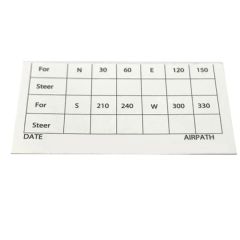
- Head aircraft in successive magnetic 30-degree headings and record all errors on the deviation card furnished with the compass.
For satisfactory results, all extraneous magnetism causing over 30-35 degree compass errors should be removed from the aircraft, or the compass should be relocated to a position where uncompensated error does not exceed 30-35 degrees. Use a brass or other non-ferrous material screwdriver when making compensator adjustments.
Best results can be obtained in actual flight compensation by following the procedure outlined below:
- Set directional gyro from a sectional line or runway. (Allow for magnetic variation to ensure gyro corresponds to magnetic heading)
- Follow procedures 1 through 6 above.
- Re-check directional gyro occasionally for possible precession, and allow for such precession error in recording results on magnetic compass deviation card.
NOTE: If aircraft is equipped, GPS can be used (allow for deviation) to establish reference headings for compass compensation. This technique will eliminate possible errors caused by gyro precession.
For any questions please contact Airpath Instrument Company at the address or phone numbers listed above.
COMMON COMPENSATION PROBLEMS
Any time there is a maintenance or repair to your aircraft, it is recommended that the compass be compensated. This is particularly true if there is work associated with the removal of old and/or installation of new equipment in the instrument panel. New radios and relocation of speakers or intercoms could affect the compensation required. New hardware (i.e. screws, nuts, etc.) installed during maintenance can sometimes be the cause of excessive errors if the hardware is steel or magnetic.
Loose electrical grounds, lighting, or extended periods of parking in North-South alignment on the ramp can lead to the magnetization of the airframe itself. This is often evidenced by excessive uncompensated compass error (more than 30-35 degrees). Engine mounts on single engine aircraft and center windshield posts becoming magnetized can lead to compensation problems. demagnetizing (degaussing) the airframe component or relocating the compass will solve this problem.
Remember that every aircraft is different. Following the set-up procedures outlined above prior to compensation is important. As stated, in-flight compensation will achieve the best results. Landing gear position can sometimes affect deviation. Other factors to consider are: yoke position, cruise configuration, pilot heat, and de-icing equipment (particularly windshield anti-ice).
Operators should consider removing any jewelry while compensating compasses. Such things as watches, rings, and eyeglasses can affect the amount of compensation required. If above method does not give satisfactory results, determine the amount of uncompensated error by aligning the reference dots on the compensator adjustment screws and frame or by removing the compensator assembly from the compass. If the uncompensated error is in excess of 30-35 degrees, troubleshoot for magnetization of aircraft components or excessive electrical interference.
TSO Index of Articles
TSO Index of Articles Information
TSO Number:
TSO-C7C
TSO Title:
Direction Instrument, Magnetic Non-Stabilized Type (Magnetic Compass)
Latest Update:
TSO Holder's Name:
Airpath Instrument Company
TSO Holder's Address:
13150 Gist Road
Bridgeton MO 63044
United States
Responsible Office:
ACE-115W Wichita Aircraft Certification Office Tel: (316) 946-4100
Part/Model Number & Name:
C-2000 thru 2500
CB-2100 ( )
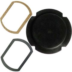
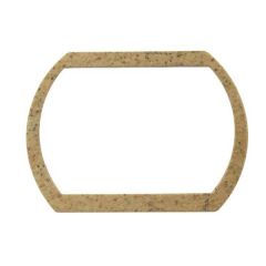
There are many inquiries about the shelf life for commercial diaphragms. Our manufacturer, of the original material, states that the shelf life is indefinite as long as the material is kept clean and at a constant, stable temperature. Once the diaphragm is installed in the compass, under harsh weather conditions, exposed to compass fluid and UV light, we warranty them for two years. On average, the compass will not leak for 5-10 years dependent upon the conditions. All of that said, we have placed a 2-year shelf life from the date the material arrives at our customer's dock. Please be advised that we strongly recommend that these diaphragms be installed by FAA licensed overhaul/repair stations only.