BECKER AR6201-022 VHF Transceiver
Manufacturer Part Number: AR6201-022
Becker AR6201–022 VHF Transceiver
General Description
Becker AR6201-022 6 Watt VHF Transceiver - is a panel mount transceiver with a sunlight readable LC display, 6W power output, 8.33/25kHz channel spacing, sensitive receiver, VOX intercom and many other features. The front panels provide enhanced user safety with the automatic safe–lock system, avoiding improper or unwanted handling. Becker Avionics introduces its new high performance, compact, AR6201 VHF–AM Transceiver with an integrated voice activated (VOX) intercom system for up to four passengers. The AR 6201 continues the legacy of its predecessor the AR4201 VHF–AM transceiver, which has set the benchmark for reliability and performance. With more than 18.000 units sold, the AR4201 has been the trustworthy for thousands of pilots flying millions of flight–hours.
The AR6201 is built using state–of–the–art DSP (Digital Signal Processing) technology resulting in a highly efficient transmitter and very sensitive receiver. The AR6201 represents a quantum leap forward in technology, performance, technical sophistication and robustness.
By blending a VHF–AM Transceiver and voice-activated (VOX) intercom system into one single, attractive unit the operator will not need to invest in a separate intercom system (up to four seats). Further, the new dual monitor mode allows two channels to be received to provide the ability to scan for radio traffic with the built-in intercom. The AR6201 display color and lighting will be compatible to the BXP6401 in the colors “green” and “white-blue”. An automated built-in–test procedure increases flight safety and reliability. The AR6201 is mountable in a 2¼″ standard instrument hole. The AR6201 will be pin–to–pin compatible with the AR4201 in order to ensure easy upgrade and replacement.
- Compact and lightweight
- Sunlight-readable display
- Robust and maintenance-free design
- No forced cooling
- No ventilation slots
- Market-leading durability
- 2-year warranty
W&W typically stocks Becker AR6201-022 VHF Transceiver.


| POWER SUPPLY DATA |
| Nominal supply voltage range | 11.0 … 30.3 V DC |
| Abnormal supply voltage range | 10.25 V … 32.2V DC |
| Emergency operation | 9.0 V DC … 10.25 V DC |
| Power consumption | |
| Power off state | ≤ 1.5 mA @ 12 V DC |
| Reception mode | ≤ 140 mA @ 14 V DC, panel backlight off |
| Reception mode | ≤ 2 A @ 14 V DC, 70 % modulated, VSWR = 1:1 |
| ≤ 4 A @ 14 V DC; 70 % modulated, VSWR = 3:1 | |
| DC–Fuse internal | 5 A (resetable) |
| Dimming control | 14 V DC or 28 V DC |
| GENERAL DATA |
| Frequency range | 118.000 MHz to 136.9916 MHz (8.33+25 kHz mode) |
| Channel spacing | 25 kHz/8.33 kHz |
| Number of channels | 760 (25 kHz mode) |
| 2280 (8.33 kHz mode) | |
| Storage temperature range | –55 °C to +85 °C |
| Operating temperature range as per EUROCAE/RTCA ED–14E/DO–160E | –20 °C to + 55 °C short–time + 70 °C |
| Operating altitude as per EUROCAE/RTCA ED–14E/DO–160E | 35,000 ft |
| Vibration as per EUROCAE/RTCA ED–14E/DO–160E | Category S (Curve M) + Category U (Curve G) |
| DIMENSIONS & WEIGHTS |
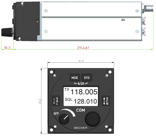
| Front panel | 61.2 mm x 61.2 mm |
| Depth of unit | 211.4 mm (front plate till end of antenna connector) |
| Mounting (backpanel) | standard 58 mm diameter (21/4 inch) |
| Material of Case | ALMg |
| Surface treatment | control head coated with black matte paint |
| Weight | 850 g |
| RECEIVER DATA |
| Sensitivity | ≤ –101 dBm for a (S+N)/N ratio of 6 dB (nominal) |
| ≤ –93 dBm for a (S+N)/N ratio of 6 dB | |
| (qualified under environmental conditions) | |
| Effective bandwidth * | ≥ ± 2.78 kHz at the 6 dB points |
| (8.33 kHz channel) | ≤ ± 7.37 kHz at the 60 dB points |
| Effective bandwidth | ≥ ± 8 kHz at the 6 dB points |
| (25 kHz channel) | ≥ ± 22 kHz at the 60 dB points |
| Squelch | trigger level adjustable |
| AGC characteristic | ≤ 6 dB in range –93 dBm to 0 dBm |
| Distortion m = 85% | ≤ 15% |
| Audio frequency response | ≤ 6 dB 350 Hz to 2500 Hz |
| relative to 1000 Hz | ≥ 35 dB at 4000 Hz |
| Rated output for speaker operation | ≥ 4 W into 4 Ω |
| Rated output power | ≥ 300 mW into 150 Ω |
| for headphone operation | ≥ 100 mW into 600 Ω |
| Audio auxiliary input | 1 V to 8 V (adjustable) across 600 Ω ± 10% |
| TRANSMITTER DATA |
| Output power | ≥ 6 W into 50 Ω (with and without modulation) |
| Frequency tolerance | ≤ 5 ppm |
| Duty cycle | 1 minute (TX) : 4 minutes (RX) |
| Type of modulation | A3E (amplitude modulation) |
| Modulation capability | ≥ 70% |
| Distortion at 70% modulation | ≤ 15% |
| Modulation bandwidth | ≤ 6 dB, 350 Hz to 2500 Hz |
| Dynamic microphone (with compressor) |
1 … 20 mV compressor starting point, adjustable Input balanced, 200 Ω Input range up to 30 dB above compressor starting point. |
| Standard microphone (with compressor) |
10 … 1000 mV compressor starting point, adjustable Input unbalanced, 150 Ω Input range up to 30 dB above compressor starting point. |
| FM deviation with modulation | ≤ 3 kHz |
| Sidetone | adjustable |
| Automatic shutdown of transmit mode | 120 seconds |
| EMERGENCY OPERATION |
| TX Output power | ≥ 2 W into 50 Ω (with modulation) |
| TX Modulation Depth | ≥ 50 % |
| RX Sensitivity | ≤ –93 dBm for a (S+N)/N ratio of 6 dB |
| Panel & Display Backlight | switched off |
| Speaker Output | switched off |
| Headphone Output | operating |
| Circuit Breaker | 7.5 AMP |


- Manuals
- Operating Instructions
- The device(s) as ordered.
- Authorized Release Certificate (EASA Form 1)
The AR6201 is intended for use with standard aviation accessories. The following equipment is required for installation:
- VHF COMM Antenna with cable and BNC connector
- Microphone
- Headphone or Speaker
Installation Wiring
Connection to the following equipment is required as minimum for AR6201
- Power Supply
- Antenna
- Microphone (direct or via external audio panel)
- Headphone or Speaker (direct or via external audio panel)
Antenna Installation
The AR6201 requires a standard 50 Ohm vertically polarized VHF antenna. Follow the antenna manufacturer's installation instructions for mounting it. In addition consider the following recommendations:
- The antenna should be mounted on a metal surface or a ground plane with a minimum area of 30 x 30 cm.
- The antenna should be mounted as much as possible away from GPS antennas (not less than 50 cm).
- The COMM antenna should also be mounted as far apart as practical from ELT antenna. Some ELTs have exhibited re–radiation problems generating harmonics that may interference with GPS signals. This can happen when COMM (AR6201 or any other) is transmitting on certain frequencies such as 121.5 MHz 121.175 MHz, which may cause the ELT output circuit to oscillate from the signal coming in on the ELT antenna connector.
Features
- 8.33kHz
- 25 kHz channel spacing
- 6 W power output
- RF signal indicator in the Display
- Dual watch function (“SCAN Mode” for monitoring a second frequency).
- VOX-controlled intercom
- 4-place intercom
- 2 separate intercom circuits
- Separate PTT for pilot and co-pilot
- Audio Auxiliary input
- Tandem Operation
- EASA certified
- FCC approved for 25 kHz versions


